VSP setup
To configure the parameters you need Mission Planner or DroneCAN GUI Tool.
Also make sure the electrical part is set up.
Parameters
| Parameter | Range | Desc |
| VSP1_RADIUS | 25-300 | Sets the radius of the ring limiter itself. Begin with conservative values. |
| VSP1_X_CENTER | 1000-2000 (1500) | Calibration of the X-axis servo center of the VSP1. Default 1500 |
| VSP1_X_CHANNEL | 1-32 | Servo channel to assign to the X-axis servo of the VSP1 |
| VSP1_Y_CENTER | 1000-2000 (1500) | Calibration of the Y-axis servo center of the VSP1. Default 1500 |
| VSP1_X_CHANNEL | 1-32 | Servo channel to assign to the Y-axis servo of the VSP1 |
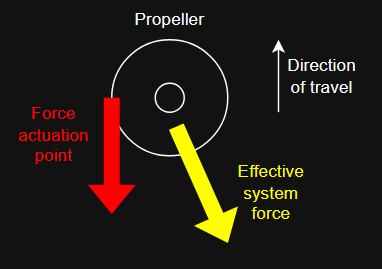
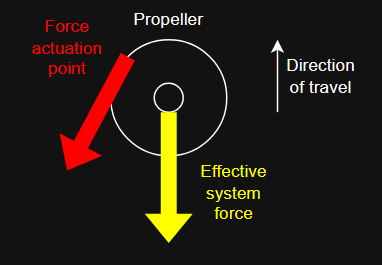
| VSP1_THRUST_ANGLE | 0-359 (0) | Thrust angle correction |
| VSP1_ESC_CHANNEL | 1-32 | Servo channel to assign to the Y-axis servo of the VSP1 |
| VSP1_ESC_SPINUP | 1000-2000 (1300) | Initial PWM pulse to the motor to avoid rotor stuck |
| VSP1_ESC_RPM1 | 100-1000 | Begin RPM value for RPM curve |
| VSP1_ESC_RPM2 | 100-1000 | End RPM value for RPM curve |
Thrust angle
RPM ramp
The controller maps a PWM input signal (in microseconds) to an RPM setpoint using a deadband region and a linear interpolation range.
Input behavior:
- ≤ 1450 µs The RPM setpoint is 0 and the motor is disabled.
- 1500 µs The RPM setpoint is RPM1.
- 2000 µs The RPM setpoint is RPM2.
- 1500–2000 µs The RPM setpoint is computed by linear interpolation between RPM1 and RPM2.
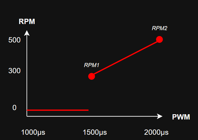
If RPM1 = RPM2, the output becomes a fixed RPM once the input exceeds 1500 µs. The region ≤ 1450 µs provides a defined off state and reduces sensitivity around the lower transition threshold.
Using a 3-way switch or potentiometer on an RC transmitter
This RPM mapping is compatible with both discrete (switch) and continuous (potentiometer/knob) input sources, as long as the transmitter outputs a standard PWM signal (typically 1000–2000 µs or 1100–1900 µs depending on configuration).
| Switch position | PWM signal | Result |
|---|---|---|
| Low | ≤ 1450 µs | Motor OFF |
| Mid | ~1500 µs | RPM = RPM1 |
| High | ~2000 µs | RPM = RPM2 |
WIth only two operating speeds are used (RPM1 and RPM2).
Potentiometer / knob (continuous control)
A potentiometer or rotary knob provides a continuous PWM range mapped across the full curve.
| Parameter | Value / Range | Purpose |
|---|---|---|
| Minimum output | ≤ 1450 µs | Ensures reliable OFF state (deadband) |
| Mid position | ~1500 µs | Defines RPM1 reference point |
| Maximum output | 2000 µs | Defines RPM2 reference point |
- ≤ 1450 µs Motor is OFF, Deadband prevents unintended activation
- 1500 µs Output = RPM1, Acts as lower active reference point
- 1500–2000 µs = Linear interpolation between RPM1 and RPM2, Smooth RPM transition across full range
- 2000 µs Output = RPM2, Maximum defined speed